What Is MTCS Modified Fumed Silica
2026-09-02
Uncategorized

Introduction

MTCS Modified Fumed Silica is a type of hydrophobic fumed silica produced by chemically treating the surface of hydrophilic fumed silica with methyltrichlorosilane (MTCS). Through this modification process, reactive silanol groups (-SiOH) on the silica surface are replaced by hydrophobic methyl groups (-CH₃), significantly reducing moisture absorption and improving compatibility with non-polar systems.

As a result, MTCS modified fumed silica exhibits excellent rheological control, anti-settling properties, thickening efficiency, and moisture resistance, making it an essential additive in adhesives, sealants, coatings, silicone rubber, and composite materials.

How Is MTCS Modified Fumed Silica Produced?

The production process begins with hydrophilic fumed silica obtained through flame hydrolysis of silicon tetrachloride (SiCl₄). The silica is subsequently treated with MTCS under controlled conditions.

During the reaction, surface hydroxyl groups react with MTCS molecules to form stable Si–O–Si bonds while introducing hydrophobic methyl groups onto the silica surface.

This surface modification changes the interaction between silica particles and surrounding media, resulting in enhanced hydrophobicity and improved dispersion behavior in many organic systems.

Key Characteristics of MTCS Modified Fumed Silica

Compared with hydrophilic fumed silica, MTCS modified grades offer several significant advantages:

  • Excellent hydrophobicity
  • Low moisture absorption
  • Superior thickening efficiency in non-polar systems
  • Outstanding anti-settling performance
  • Improved storage stability
  • Enhanced flow control and rheology adjustment
  • Good dispersibility in organic media

These properties make MTCS modified grades particularly suitable for formulations exposed to humid environments.

Typical Applications

1. Silicone Sealants and RTV Systems

MTCS modified fumed silica is widely used in RTV silicone sealants and silicone adhesives. It provides effective reinforcement, sag resistance, and viscosity control while maintaining excellent storage stability.

2. Adhesives and Sealants

In polyurethane, MS polymer, and hybrid adhesive systems, MTCS modified silica improves rheology, prevents filler sedimentation, and enhances long-term performance.

3. Paints and Coatings

Hydrophobic fumed silica is commonly employed as a rheology modifier and anti-settling agent in industrial coatings, marine coatings, and protective coatings.

4. Composite Materials

The excellent compatibility of MTCS modified silica with organic resins makes it valuable in composite applications where mechanical strength and processing stability are required.

MTCS Modified vs Hydrophilic Fumed Silica

Property MTCS Modified Fumed Silica Hydrophilic Fumed Silica
Surface Chemistry Methyl-treated Silanol-rich
Water Affinity Hydrophobic Hydrophilic
Moisture Absorption Very Low High
Organic Compatibility Excellent Moderate
Anti-Settling Performance Excellent Good
Use in Sealants Highly Recommended Limited

Conclusion

MTCS Modified Fumed Silica is one of the most widely used hydrophobic fumed silica products in the market today. By replacing surface hydroxyl groups with methyl groups, it delivers superior moisture resistance, rheological performance, and formulation stability.

For applications such as silicone sealants, adhesives, coatings, and composites, MTCS modified fumed silica remains a highly effective solution for improving product performance and processing efficiency.

As a trusted fumed silica manufacturer, GESEESIL offers high-quality MTCS modified fumed silica grades designed to meet the demanding requirements of sealants, adhesives, coatings, and advanced material applications. Our products provide excellent hydrophobicity, rheological control, and long-term formulation stability, helping customers achieve consistent and reliable performance.


Bottled Nitrogen vs On-site PSA Nitrogen Generator Which Is Better for Your Business
2026-08-28
Uncategorized


Industrial nitrogen supply mainly relies on two mainstream solutions: bottled nitrogen and on-site PSA nitrogen generation. Each solution has its unique advantages and applicable scenarios. Many factory managers and system integrators struggle to select the most cost-effective and reliable gas supply mode according to their production conditions. This article makes an objective, all-round comparison of the two nitrogen supply methods in terms of cost, stability, safety and applicability, helping enterprises make rational decisions.


1. Cost Comparison


1.1 Bottled Nitrogen 

Advantage: No upfront equipment investment, no equipment maintenance costs. For enterprises with extremely low gas consumption or temporary experimental production, bottled nitrogen avoids idle asset waste and saves early equipment deployment costs.

Disadvantage: Long-term comprehensive cost is high. Continuous gas purchase, cylinder rental, transportation and manual replacement fees form recurring expenditure. Gas prices are easily affected by market fluctuations and supplier adjustments, leading to uncontrollable long-term operating costs.


1.2 PSA Nitrogen Generator

Disadvantage: One-time upfront investment is required for equipment purchase and installation, which raises the initial project budget threshold for enterprises.

Advantage: The long-term operating cost is extremely low. The equipment only consumes electric energy and compressed air during operation. After recovering the upfront investment, enterprises can obtain almost free stable nitrogen supply, completely getting rid of reliance on external gas suppliers.


2. Gas Supply Stability & Flexibility


2.1 Bottled Nitrogen

Advantage: The nitrogen purity of finished cylinders is fixed and high, with stable single-batch gas quality. It is suitable for ultra-high-purity gas demand scenarios with no need for parameter adjustment, and no professional equipment debugging is required on site.

Disadvantage: The gas supply is dependent on external logistics and suppliers. It is easy to face gas shortage, delayed delivery and production interruption during peak seasons or supplier stock shortages. In addition, the purity and pressure of different batches of bottled gas have subtle deviations, which is not conducive to high-standard continuous production.


2.2 PSA Nitrogen Generator

Disadvantage: The gas purity and pressure need regular minor debugging according to ambient temperature and equipment operation status, requiring basic daily inspection and maintenance.

Advantage: It supports 24/7 uninterrupted on-demand gas supply. The nitrogen purity and pressure can be freely adjusted within the equipment range, matching different production process requirements. The gas quality is consistent and not affected by external supply chains.


3. On-site Safety & Operation Management


3.1 Bottled Nitrogen

Advantage: No professional equipment operation training is required, no mechanical failure risks. The whole process is simple and labor-saving for short-term and intermittent gas use.

Disadvantage: A large number of high-pressure gas cylinders stored in the workshop occupy production space. Frequent handling and replacement of heavy cylinders bring potential high-pressure safety hazards and increase labor pressure.


3.2 PSA Nitrogen Generator

Disadvantage: The equipment occupies a certain workshop area and requires regular inspection of air compressors, filters and core consumables.

Advantage: Fully automatic unmanned operation after commissioning, no frequent manual operation. It eliminates hidden dangers of high-pressure cylinder storage and handling, making the production site safer and more standardized.


4. Applicable Scenario Analysis


4.1 Choose Bottled Nitrogen If:

Your factory has low gas consumption, discontinuous and intermittent production, short-term pilot projects, or ultra-high-purity nitrogen demand that does not require parameter adjustment.


4.2 Choose PSA Nitrogen Generator If:

You need long-term, stable, and continuous gas supply, including oil & gas, chemical, food packaging, electronic manufacturing, mining and other industrial scenarios. It is the optimal solution for mass and standardized production.


Final Conclusion

Bottled nitrogen is flexible and zero-investment in the early stage, suitable for small and intermittent gas demand.

However, for most industrial enterprises with long-term and stable production, on-site PSA nitrogen generators have absolute advantages in cost control, gas supply stability and on-site safety. The stable operation of PSA nitrogen equipment is inseparable from high-quality carbon molecular sieve (CMS), which is the core consumable to ensure long-term stable and high-purity nitrogen production.

If you need high-quality carbon molecular sieve for new equipment assembly or old equipment replacement to optimize your PSA nitrogen system performance, feel free to contact our professional team for technical support and customized quotation.

Please click www.carbon-cms.com. Reach out to us if you need further guidance for carbon molecular sieve application. 


Practical Advice For Carbon Molecular Sieve Storage & Managemen
2026-08-28
Uncategorized


Many storage-related issues will negatively affect the performance of carbon molecular sieve (CMS). Proper storage and daily management help preserve adsorption capacity and extend service life. We have sorted out universal practical tips for global PSA nitrogen operators, equipment manufacturers and distributors. 


1.Keep Away From Moisture

Carbon molecular sieve is highly hygroscopic. Once it absorbs water vapor in the air, its separation performance will decline significantly. 

  • Keep CMS sealed in original packaging before use. Do not open the bags in humid environments. 
  • Avoid storing goods outdoors or in areas prone to rain, dew and water splashing.


2.Avoid Exposure To Oil Vapor & Contaminants 

Oil mist, volatile chemical gas and dust can cause irreversible contamination to carbon molecular sieve. 

  • The warehouse should be kept clean. Do not place CMS together with lubricants, solvents or corrosive materials. 
  • Prevent heavy dust accumulation on packaging. 


3.Reasonable Warehouse Environment 

  • Store CMS indoors in cool and dry conditions, away from high temperature and direct sunlight. 
  • The recommended storage temperature ranges from 15℃ to 30℃, with relative humidity below 70%RH. 
  • The storage space needs good ventilation, with stable ambient temperature.
  •  Keep the ground dry. Place pallets under CMS packages instead of directly stacking goods on the floor. 


4.Stacking & Handling Notes 

  • Do not excessively stack packages to prevent bag breakage and material powdering caused by extrusion. 
  • Avoid violent throwing during loading and unloading. Broken packages will lose sealing protection quickly. 


5.Short-term Storage After Opening Packaging 

If you have opened the packaging but cannot fill the PSA vessel immediately: 

  • Seal the opening tightly again. Arrange loading as soon as possible. 
  • Do not leave carbon molecular sieve exposed to atmosphere for a long time.


Final Reminder 

Standardized storage is a low-cost way to protect your investment in carbon molecular sieve. If you have any questions about CMS handling before loading, feel free to contact our team for support. 


Please click www.carbon-cms.com. Reach out to us if you need further guidance for carbon molecular sieve application. 

PSA vs Membrane Nitrogen Generator Which One Should You Choose for Your Plant
2026-08-28
Uncategorized


On-site nitrogen generation has become the mainstream choice for modern industrial gas supply. The two most widely adopted technical solutions are PSA (Pressure Swing Adsorption) nitrogen generation and membrane nitrogen generation.

Many buyers and system integrators misunderstand that membrane technology is outdated or eliminated. In fact, both technologies are mature and coexist in the market, with their unique working principles, advantages and targeted application scenarios.

Choosing the right solution according to actual production needs is the key to balancing cost and operational efficiency.


1. Working Principle Difference


1.1 PSA Nitrogen Generator

PSA nitrogen generation relies on carbon molecular sieve (CMS) as the core filter material. Under variable pressure conditions, CMS selectively adsorbs oxygen, moisture and impurity gases in compressed air, allowing nitrogen to pass through and be collected. It realizes gas separation through periodic pressure adsorption and desorption cycles.


1.2 Membrane Nitrogen Generator

The core component is hollow fiber membrane modules. It adopts physical permeation separation without any adsorbent consumables. Compressed air enters the membrane fibers; fast-permeating gases such as oxygen, water vapor and carbon dioxide penetrate the membrane wall and are discharged. Slow-permeating nitrogen is retained and collected to form finished nitrogen gas.


2. Membrane Nitrogen


2.1 Objective Advantages

Membrane nitrogen technology is not obsolete equipment. It features simple structure, no moving parts, no valve switching action, and ultra-low failure rate. It can produce qualified nitrogen instantly after startup without preheating or waiting.

The whole machine is compact, vibration-free, easy to install and move, and requires almost no daily maintenance. With low initial investment, it is very suitable for lightweight and intermittent gas demand scenarios.


2.2 Inherent Limitations

Restricted by physical permeation principles, membrane systems have a fixed purity ceiling. The stable nitrogen purity range is 90%–98%. It is difficult and extremely energy-consuming to achieve nitrogen purity above 99.5%.

In high-temperature and high-humidity environments, membrane permeability decreases, resulting in reduced gas production and unstable purity. In addition, membrane components have natural performance attenuation after long-term operation.


3.PSA Nitrogen


3.1 Objective Advantages PSA

PSA nitrogen generators have ultra-wide purity adjustment range, stably covering 95%–99.999% nitrogen purity. It fully meets high-standard production demands such as chemical inerting, electronic manufacturing, food fresh-keeping and oil & gas explosion-proof.

Supported by high-quality carbon molecular sieve, PSA systems feature strong anti-interference ability, stable long-term operation, unaffected by ambient temperature and humidity, and excellent consistency of outlet gas quality.


3.2 Inherent Limitations PSA

PSA equipment has a relatively complex system with air compression, filtration and adsorption tower modules, requiring a certain installation space.

Regular inspection and replacement of filter elements and CMS consumables are needed. Compared with membrane equipment, it has slightly higher daily maintenance requirements and initial investment costs.


4.Scenario-based Selection Guide


4.1 Choose Membrane Nitrogen Generator If:

  • Low and intermittent nitrogen consumption;
  • Required nitrogen purity ≤ 98%;
  • Limited on-site space, mobile or outdoor working conditions
  • Unmanned long-term standby use with minimal maintenance demand


4.2 Choose PSA Nitrogen Generator If:

  • Long-term, continuous and stable industrial gas demand;
  • Nitrogen purity ≥ 99% (especially high purity above 99.9%);
  • Strict requirements for gas quality stability and production consistency;
  • Industrial scenarios such as petrochemical, electronics, new energy and mining.


Final Conclusion

There is no absolute superior or inferior between PSA and membrane nitrogen generation technologies. Membrane technology is the optimal solution for low-purity, lightweight, and low-maintenance scenarios. PSA nitrogen generation is the mainstream industrial solution for high-purity, high-stability and long-term continuous production.

The stable performance of PSA equipment is closely related to the quality of carbon molecular sieve. High-quality CMS ensures long-term stable adsorption efficiency, consistent gas purity and extended service life of the whole system.

If you are looking for high-performance and stable carbon molecular sieve for PSA nitrogen equipment assembly or replacement, welcome to contact our team for professional technical support and customized quotation.


Please click www.carbon-cms.com. Reach out to us if you need further guidance for carbon molecular sieve application. 


SHANLI In-house Laboratory What Testing Services We Offer For PSA Nitrogen Partner
2026-08-28
Uncategorized


Many carbon molecular sieve suppliers only provide finished products with basic datasheets. At Shanli, our in-house testing lab is an important part of our technical service for OEM manufacturers, system integrators and end-users of PSA nitrogen generators.


We do not just sell carbon molecular sieve particles. Our laboratory carries out a full set of professional tests to verify CMS real-world performance, simulate your actual working conditions, and support your product development and equipment upgrading.


1.Our core lab testing capabilities


1.1 Dynamic and Static Adsorption Testing

We test static and dynamic adsorption capacity of every batch of CMS. This helps us confirm oxygen-nitrogen separation performance and guarantee consistent adsorption capability batch after batch.


1.2 Performance Testing Under Different Adsorption Pressures

PSA systems run under various working pressure ranges. Our lab simulates different adsorption pressure environments, to check how our carbon molecular sieve performs under your target operating pressure. This supports you for adsorber vessel design and parameter tuning.


1.3 Performance Testing Under Varying Ambient Temperature

Ambient temperature greatly affects PSA nitrogen output and purity. We run tests across different temperature conditions, simulating tropical high-temperature sites or low-temperature working scenarios for your overseas projects.


1.4 Air Consumption Testing Under Different Conditions

Air consumption is a key economic indicator for PSA nitrogen plants. We test air-to-nitrogen ratio under multiple working setups. The test data can help you optimize your equipment design and reduce customers’ operating cost.


1.5 Process Compatibility Testing For PSA Equipment

We perform full process compatibility testing matching real PSA equipment workflow. Before large-volume delivery, we can simulate your PSA cycle parameters to verify whether our carbon molecular sieve fits your machine perfectly. This greatly reduces risks for your new-machine trial or replacement projects.


2.What value can these lab services bring to you?


2.1 Reliable batch consistency

Every batch is tested, you will receive complete test reports together with goods.


2.2 Customized technical support

If you have special working conditions, we can run targeted lab simulation tests for your project.


2.3 Lower trial-and-error risk

Verify performance in our lab first, before you do expensive on-site machine testing.


2.4 Data for your equipment R&D

Provide real test data for your new PSA equipment development.


Whether you need standard-grade carbon molecular sieve, or require custom development for special PSA working scenarios, our lab team can offer you solid testing support.


If you want to learn more about our laboratory testing service, or require test support for your PSA nitrogen project, please feel free to contact our technical team. 


Advanced Composite Materials Fuel the Rise of the Low-Altitude Economy
2026-08-13
Uncategorized

Advanced Materials Driving the Future of Low-Altitude Economy: Lightweighting, Performance and Future Manufacturing


In 2026, the low-altitude economy is entering a milestone phase driven by supportive policies, positioning itself as a new strategic pillar industry.


Behind this trillion-yuan market transformation lies a fundamental factor that determines the performance boundaries and commercial success of next-generation aircraft — advanced materials. Industry analysis indicates that advanced materials currently account for approximately 30%–50% of aircraft material costs. As the low-altitude economy expands beyond the RMB 1 trillion market scale, the demand for advanced materials is projected to exceed RMB 500 billion, creating significant opportunities for high-performance composite materials.


1. Lightweighting: A Competition Measured in Every Gram


For low-altitude aircraft, weight is the strictest “accountant.” Unlike traditional fuel-powered aircraft, electric low-altitude aircraft rely on batteries for energy supply.

Every additional kilogram means reduced flight range and lower payload capacity. The industry often refers to the principle that “every kilogram saved can add 10 kilometers of range.” Therefore, every weight reduction in the fuselage, wings, and rotors can translate into longer flight distances, higher payload capacity, or greater safety margins.


Carbon fiber composites are considered the ultimate solution to this challenge. With a density only about one-quarter that of steel while offering tensile strength more than nine times higher, carbon fiber composites can significantly reduce aircraft weight when replacing traditional metal materials. Compared with conventional aluminum alloys, carbon fiber composites can achieve 20%–40% structural weight reduction. Thanks to their outstanding combination of lightweight properties, high strength, high stiffness, corrosion resistance, and fatigue resistance, carbon fiber composites have become an ideal material choice for eVTOL structures and are often referred to as “black gold.”


In eVTOL (electric vertical takeoff and landing aircraft), composite materials are mainly used in structural components and propulsion systems, accounting for approximately 75%–80% of the total aircraft structure. Composite materials represent more than 70% of an eVTOL’s structural composition, with carbon fiber composites accounting for around 90% of the composite materials used. They are widely applied across primary and secondary load-bearing structures and functional components, including fuselages, rotors, wings, battery enclosures, propulsion blades, seats, and various brackets.


Depending on aircraft size and payload requirements, a single passenger eVTOL may require 100–400 kg of carbon fiber composite materials. Industry forecasts suggest that between 2024 and 2030, carbon fiber demand from the eVTOL sector alone will surge from 500 tons to 11,700 tons, representing an average annual growth rate of approximately 69%, with the market expected to expand by 22.5 times within six years.


A cargo drone model has achieved a 40% weight reduction through an all-carbon-fiber fuselage design, extending its flight range to 280 km. The XPeng Voyager X2 adopts carbon fiber materials throughout its airframe to achieve a balance between lightweight design and structural safety, while AutoFlight V2000CG also incorporates high-strength carbon fiber composite technologies in its core structure.


Nylon 12 Carbon Fiber Reinforced


2. Foam Core Materials: The “Invisible Skeleton” Inside Sandwich Structures


Beyond the carbon fiber composite “skeleton” of low-altitude aircraft, foam core materials serve as an indispensable “invisible backbone” within sandwich structures. Their core value lies in providing extremely high specific stiffness and buckling resistance to composite skins while maintaining ultra-low weight, achieving a structural efficiency where “1+1>2.”


Currently, foam core materials used in low-altitude aircraft mainly follow a dual-material landscape dominated by PMI foam and PVC foam, each serving different performance and cost requirements.


PMI foam (Polymethacrylimide foam) is a key core material designed to meet the combined demands of extreme lightweighting, structural rigidity, thermal resistance, and flame-retardant performance. Its primary role is to enable the manufacturing of large-scale integrated sandwich structures, including wings, fuselage sections, and rotor blades. Thanks to its closed-cell microstructure and inherent thermal stability, PMI foam provides a passive safety barrier that helps resist heat penetration while maintaining structural integrity under high-temperature conditions.


In the eVTOL sector, PMI foam core materials have become the dominant choice for high-performance applications. ROHACELL PMI foam developed by Evonik, known for its ultra-lightweight characteristics and high mechanical strength, has already been applied in the design of critical eVTOL structural components. Industry forecasts indicate that a single eVTOL aircraft may require up to 50 kg of PMI foam core materials. The global eVTOL PMI foam market reached approximately USD 250 million in sales in 2025 and is projected to grow to USD 707 million by 2032, representing a compound annual growth rate (CAGR) of 16.0%.


PVC foam core materials, on the other hand, have gained widespread adoption in fixed-wing UAV applications due to their cost advantages. Structural PVC foam features a high closed-cell ratio, excellent mechanical properties, temperature resistance, and chemical corrosion resistance. In the eVTOL field, PVC foam cores are mainly used in non-load-bearing structures such as cargo compartments of cargo aircraft models.


In addition, materials such as PET foam and balsa wood cores are also utilized in specific applications, together forming a diversified core material system for sandwich structures in low-altitude aircraft.


3. Metallic Materials: From “Foundation” to “Critical Structural Support”


Although carbon fiber composites are gaining an increasing share of applications in low-altitude aircraft, metallic materials are far from being replaced. Instead, they continue to play irreplaceable roles in specific areas where strength, durability, reliability, and manufacturability are essential. Aluminum alloys, titanium alloys, magnesium alloys, and aluminum-lithium alloys together form a comprehensive metallic material system that enables lightweight design, high performance, and structural safety for low-altitude aircraft.

Aluminum Alloys: The Foundation Materials of Low-Altitude Aircraft

With advantages including low density (approximately 2.7 g/cm³), excellent corrosion resistance and good manufacturability, aluminum alloys remain among the most widely used structural materials.


With advantages including low density (approximately 2.7 g/cm³), excellent corrosion resistance, and good manufacturability, aluminum alloys remain among the most widely used structural materials in low-altitude aircraft. In the eVTOL sector, aerospace-grade aluminum alloys account for more than 60% of the fuselage structural weight, with the global market reaching approximately RMB 1.95 billion in 2026. High-strength aluminum alloys are widely applied in areas exposed to concentrated loads, including wing joints, tail connections, landing gear, and rotor structures.


According to data from the China Nonferrous Metals Industry Association, aluminum demand from the UAV sector increased by 40% year-on-year in 2025. The GOVY AirCab flying car developed by GAC Group adopts an aerospace-grade aluminum alloy frame. Beyond aircraft structures, aluminum alloys are also widely used in the construction of lightweight runways and intelligent control towers for low-altitude takeoff and landing facilities.


Titanium alloys serve as the “joints and critical components” of aircraft.

Thanks to their excellent strength-to-weight ratio, high-temperature resistance, and corrosion resistance, titanium alloys are widely used in key load-bearing components such as aircraft engines and landing gear, accounting for approximately 15%–20% of eVTOL structural weight. The latest dual-titanium alloy blade disk designs have improved propulsion system efficiency by 15%–20% while extending fatigue life by 40%.


Magnesium alloys are the “hidden champion” in the lightweighting competition.

With a density only around two-thirds that of aluminum alloys, magnesium alloys offer exceptional lightweight advantages. By significantly reducing aircraft weight, magnesium alloys can improve flight range and payload capacity, accelerating their adoption in the low-altitude economy.


In eVTOL applications, components such as integrated arms, battery housings, and motor casings are gradually shifting from aluminum to large-scale magnesium alloy die-cast structures, potentially reducing overall aircraft weight by more than 30%. Magnesium-lithium alloys, with a density approximately half that of aluminum alloys, are becoming a critical solution for high-end aircraft seeking improvements in both endurance and payload capacity, especially as future lightweighting requirements continue to rise.


Aluminum-lithium alloys represent an advanced direction for achieving both strength and lightweight performance.

Primarily used in major load-bearing structures such as wing spars and fuselage frames, aluminum-lithium alloys can reduce weight by approximately 8%–10% compared with traditional aluminum alloys while maintaining structural strength.


As eVTOL commercialization and mass production accelerate, demand for aerospace-grade aluminum alloys, titanium alloys, and nickel-based high-temperature alloys is expected to experience simultaneous growth in both volume and value during the second half of 2026.


4. Special Engineering Plastics and Aramid Materials: The Indispensable “Supporting Roles”


Special engineering plastics also play an essential role in the development of low-altitude aircraft. High-performance nylon, flame-retardant polyester materials, and thermoset composites have already achieved mass production applications in consumer drones, agricultural drones, and other commercial scenarios.


Polyether ether ketone (PEEK) materials have attracted significant attention due to their outstanding combination of lightweight properties, high-temperature resistance, flame retardancy, corrosion resistance, and excellent mechanical performance. PEEK has been applied in various aircraft components, including wheel covers, fairings, seat frames, environmental control system impellers, and wing fasteners. In UAV frames and flying vehicle structural components, PEEK demonstrates significant advantages as a metal replacement material.


Thermoplastic composites based on modified polyamide (PA), polyether ether ketone (PEEK), and other high-performance polymers are seeing increasing adoption in load-bearing components and structural connection parts, driven by the demand for lightweight, integrated, and cost-efficient manufacturing solutions.


Aramid fiber composites offer excellent toughness and impact resistance, making them suitable for applications such as secondary load-bearing structures in helicopters and UAV wing skins. Aramid paper honeycomb cores and sandwich structures provide a combination of ultra-lightweight design, high strength, and impact resistance, and are widely used in aircraft interiors, radomes, and structural components.


By adopting honeycomb composite structures, aircraft manufacturers can achieve approximately 20% localized weight reduction while simultaneously improving fatigue resistance and extending service life.


PEEK Carbon Fiber Reinforced


The Future of Low-Altitude Aircraft Lies in Material Integration

The development of the low-altitude economy is not driven by a single perfect material, but by the integration of multiple advanced material systems. Carbon fiber composites provide exceptional lightweight strength, foam cores improve structural efficiency, metallic materials ensure reliability, while high-performance polymers enable lightweight and cost-efficient manufacturing.

As eVTOL aircraft and commercial drones move toward large-scale production, long fiber reinforced thermoplastic composites are expected to play an increasingly important role due to their excellent mechanical performance, impact resistance, design flexibility, and suitability for efficient manufacturing.

The future of low-altitude mobility will be shaped not only by innovative aircraft design, but also by continuous breakthroughs in advanced materials — creating aircraft that are lighter, safer, more efficient, and ready for commercialization.

Why Composites Are Replacing Metals in Marine Applications
2026-08-13
Uncategorized
Why Long Fiber Reinforced Thermoplastics Are Replacing Metals in Marine Applications | LFT-G
MARINE COMPOSITE MATERIALS

Why Long Fiber Reinforced Thermoplastics Are Replacing Metals in Marine Applications

Discover how Long Fiber Reinforced Thermoplastics (LFT) provide corrosion resistance, lightweight performance, high mechanical strength and long-term durability for demanding marine engineering applications.

Key Takeaway: In marine environments, material selection is not only about strength and weight. Corrosion resistance, service life, maintenance requirements and total lifecycle cost can be equally important. This is where fiber-reinforced thermoplastic composites offer a compelling alternative to traditional metals.

Introduction: Why Marine Engineering Needs New Materials
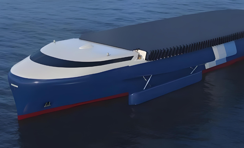
Metals have been the foundation of modern industrial development for centuries. Steel, aluminum and titanium alloys have enabled the construction of ships, offshore platforms, marine infrastructure and advanced industrial equipment.

However, when traditional metals are exposed to harsh marine environments for extended periods, they face one fundamental challenge: corrosion.

Seawater combines salt, oxygen, moisture and complex electrochemical conditions, creating one of the most demanding environments for engineering materials. Chloride ions can accelerate localized corrosion, while continuous exposure can increase maintenance requirements and shorten component service life.

For offshore wind power, shipbuilding, seawater systems, marine equipment and coastal infrastructure, corrosion is more than a material problem. It can directly influence operational safety, maintenance costs, equipment reliability and overall lifecycle economics.

As a result, engineers are increasingly looking for corrosion-resistant composite materials that can reduce dependence on traditional metal components.

Why Do Metals Corrode in Marine Environments?
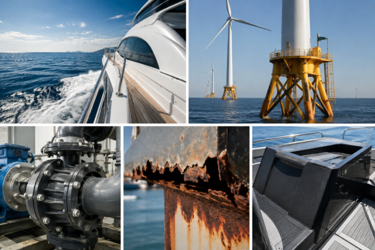
From a thermodynamic perspective, most refined metals exist in a relatively high-energy state compared with their naturally occurring mineral forms.

During metal production, significant energy is required to transform metal oxides and ores into refined metals. Over time, metals naturally tend to return toward more stable oxidized states through chemical and electrochemical reactions.

In marine environments, seawater acts as an effective electrolyte. The combination of oxygen, water and chloride ions creates favorable conditions for electrochemical corrosion.

This is why corrosion protection remains one of the most important challenges in marine engineering and offshore applications.

The Hidden Corrosion Risks of Stainless Steel

Stainless steel is widely used because its chromium-rich passive layer provides excellent corrosion resistance under many conditions. However, stainless steel should not be interpreted as completely corrosion-proof.

In marine environments, stainless steel can still experience several localized corrosion mechanisms.

Pitting Corrosion

Localized breakdown of the passive layer can create small corrosion sites that gradually develop into deep pits. These pits may penetrate significantly into the material while leaving relatively little visible damage on the surface.

Crevice Corrosion

Narrow gaps around fasteners, mechanical joints, seals and overlapping components can create oxygen-depleted conditions. These areas can become highly susceptible to localized corrosion.

Stress Corrosion Cracking

The combination of tensile stress and a corrosive marine environment can contribute to stress corrosion cracking in susceptible alloys, creating additional challenges for long-term structural reliability.

The challenge is not simply that metal corrodes. In many marine applications, corrosion can develop in areas that are difficult to inspect, repair or recoat.

From Polymer Stability to Engineering Performance

Plastics are often discussed in the context of environmental persistence. However, from an engineering perspective, the chemical stability of polymers can provide a major performance advantage.

When thermoplastic polymers are reinforced with long glass fibers or carbon fibers, their mechanical properties can be significantly improved, creating fiber-reinforced thermoplastic composites.

Unlike traditional metals, the polymer matrix does not undergo the same electrochemical corrosion mechanism responsible for rust and many forms of metal degradation.

This makes fiber-reinforced thermoplastics attractive for applications where resistance to seawater, salt spray and chloride-rich environments is important.

Why Long Fiber Reinforced Thermoplastics Are Ideal for Marine Applications
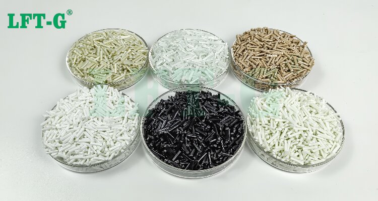

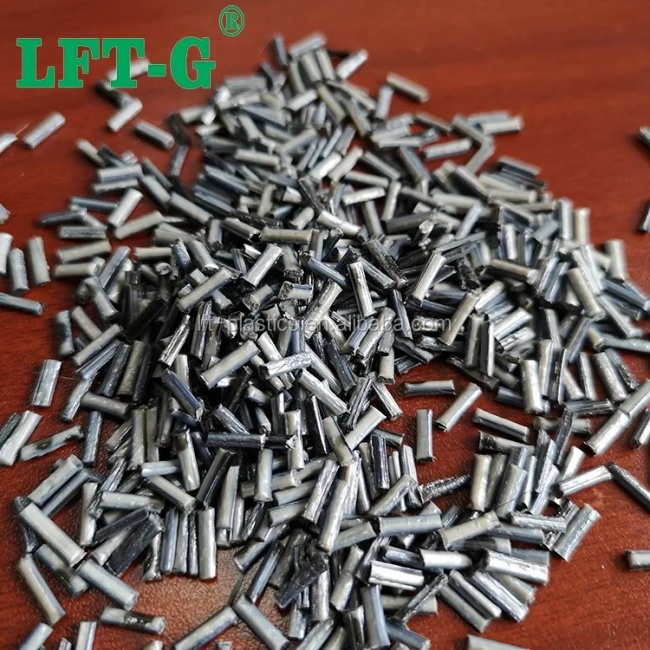
Long Fiber Reinforced Thermoplastics (LFT) combine the processing advantages of thermoplastics with the mechanical reinforcement provided by long glass fibers or carbon fibers.

This combination allows engineers to develop lightweight structural components that provide high strength, impact resistance and durability while offering excellent resistance to corrosion.

01. Corrosion Resistance

LFT materials do not rust and provide excellent resistance to seawater and chloride-rich environments, helping reduce corrosion-related maintenance.

02. Lightweight Performance

Long glass fiber and carbon fiber reinforced thermoplastics offer excellent strength-to-weight ratios, making them attractive alternatives to heavier metal components.

03. High Mechanical Strength

Long fibers improve load transfer within the polymer matrix and can provide high tensile strength, stiffness and impact resistance.

04. Manufacturing Efficiency

Thermoplastic composite materials can be processed using injection molding and other high-efficiency manufacturing technologies, supporting scalable production.

Long Fiber Reinforced Thermoplastics vs. Traditional Metals

The right material depends on the application. However, for marine components exposed to corrosive environments, LFT composites offer several important advantages.

Property Traditional Metals Fiber-Reinforced Thermoplastics
Corrosion Resistance Requires material selection and protection systems Excellent resistance to seawater and chloride environments
Weight Generally higher Lightweight
Strength-to-Weight Ratio Good Excellent for many structural applications
Maintenance May require coating, inspection and corrosion control Reduced corrosion-related maintenance requirements
Design Flexibility Dependent on machining and forming processes High design flexibility through molding technologies
Large-Scale Production Well established Highly suitable for automated thermoplastic processing

Marine Applications of Fiber-Reinforced Thermoplastics

The combination of corrosion resistance, lightweight performance and mechanical strength makes fiber-reinforced thermoplastics suitable for a growing range of marine and offshore applications.

Offshore Energy

  • Offshore wind turbine components
  • Oil and gas platform components
  • Offshore equipment housings
  • Subsea equipment components

Marine Equipment

  • Pump components
  • Valve components
  • Protective housings
  • Seawater cooling system components

Shipbuilding

  • Lightweight structural components
  • Corrosion-resistant components
  • Interior systems
  • Equipment housings

Coastal Infrastructure

  • Water treatment equipment
  • Seawater handling systems
  • Infrastructure components
  • Corrosion-resistant structural parts

Glass Fiber vs. Carbon Fiber Reinforced Thermoplastics

Both Long Glass Fiber Reinforced Thermoplastics (LGF) and Long Carbon Fiber Reinforced Thermoplastics (LCF) can be used to develop lightweight structural components, but their performance profiles are different.

Long Glass Fiber Reinforced Thermoplastics

LGF thermoplastics provide an attractive balance of mechanical strength, impact resistance, weight reduction and cost efficiency. They are suitable for many industrial and marine components where high performance and cost effectiveness are both important.

Long Carbon Fiber Reinforced Thermoplastics

LCF thermoplastics provide higher stiffness and excellent strength-to-weight performance, making them suitable for applications where structural performance and weight reduction are particularly important.

The Material Selection Dilemma: Space vs. Ocean

There is no universal material that is ideal for every engineering environment. Material selection must always consider temperature, mechanical loading, chemical exposure, manufacturing requirements, cost and expected service life.

SpaceX's Starship program provides an interesting example. Stainless steel was selected for Starship because of its performance under cryogenic conditions, resistance to extreme aerodynamic heating, manufacturing efficiency and cost advantages.

However, aerospace and marine engineering present fundamentally different challenges.

Space is a vacuum. The ocean is a continuous electrochemical environment.

A material that is highly competitive for spacecraft does not necessarily provide the best lifecycle value for a structure exposed to seawater for decades.

Why Lifecycle Cost Matters in Marine Engineering

Initial material price is only one part of the total cost of an engineering component. In marine applications, designers must also consider inspection, coating, replacement, downtime and maintenance over the entire service life.

A corrosion-resistant composite component can potentially reduce the need for corrosion protection and maintenance, helping improve the overall lifecycle economics of marine equipment.

This is particularly important for components installed in difficult-to-access locations, where inspection and replacement can be expensive or operationally disruptive.

The Future of Marine Engineering: Lightweight and Corrosion-Resistant Composites

The future of marine engineering is not about eliminating metals entirely. Different materials will continue to serve different engineering requirements.

However, as industries increasingly focus on lightweighting, energy efficiency, durability and lower lifecycle costs, advanced composite materials are becoming an increasingly important part of material selection strategies.

Long Fiber Reinforced Thermoplastics offer a compelling combination of corrosion resistance, lightweight performance, mechanical strength and manufacturing efficiency.

For marine and offshore applications where long-term exposure to seawater is a critical design factor, fiber-reinforced thermoplastic composites can provide a reliable alternative to selected metal components.

By combining advanced thermoplastic matrices with long glass fiber and long carbon fiber reinforcement, LFT-G develops high-performance composite materials designed to support the next generation of lightweight and durable engineering solutions.

Frequently Asked Questions

Why are composite materials used in marine applications?

Composite materials offer excellent corrosion resistance, lightweight performance, high strength and long-term durability, making them suitable for demanding marine environments.

What are Long Fiber Reinforced Thermoplastics?

Long Fiber Reinforced Thermoplastics are advanced thermoplastic composites reinforced with long glass fibers or carbon fibers to improve strength, stiffness, impact resistance and dimensional stability.

Can LFT materials replace metals in marine applications?

Depending on the application, LFT materials can replace selected metal components where corrosion resistance, weight reduction, mechanical performance and manufacturing efficiency are important.

Are glass fiber reinforced thermoplastics resistant to seawater?

Glass fiber reinforced thermoplastics provide strong resistance to seawater and chloride-rich environments because the thermoplastic matrix does not undergo the electrochemical corrosion mechanism associated with metals.

Looking for High-Performance Marine Composite Materials?

LFT-G develops long glass fiber and long carbon fiber reinforced thermoplastic materials for demanding industrial applications. Contact our technical team to discuss a customized material solution for your marine or offshore project.

Contact LFT-G
3 Critical Hidden Defects Inside High-Filled Thick-Wall Plastic Parts
2026-08-07
Uncategorized

3 Critical Hidden Defects Inside High-Filled Thick-Wall Plastic Parts

High glass fiber and mineral-filled plastics are widely used in automotive, appliance, and industrial structural applications because they provide excellent stiffness, strength, and dimensional stability.

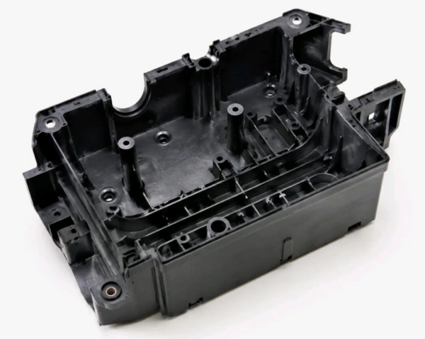
However, thick-wall molded components made from highly filled plastics are highly susceptible to hidden internal defects, including internal voids, delamination, and cold slugs.

Because these defects are hidden beneath the surface, they often cannot be detected through normal appearance inspection. During actual operation, internal defects may become stress concentration areas, causing cracks, leakage, sudden failure, and expensive batch rejection.

Hidden internal defects in high-filled thick-wall plastic parts

Table of Contents

  • Why Are Thick-Wall Highly Filled Plastic Parts More Prone to Internal Defects?
  • Internal Voids / Shrinkage Cavities
  • Delamination / Interlayer Separation
  • Cold Slugs / Internal Dark Spots

1. Why Are Thick-Wall Highly Filled Plastic Parts More Prone to Internal Defects?

Compared with highly filled plastics, conventional unfilled plastics generally have better flowability and more uniform shrinkage behavior, resulting in fewer molding risks.

However, after adding large amounts of glass fiber or mineral fillers, melt viscosity increases significantly. The material becomes more difficult to flow, fill, and pack during injection molding.

Two Major Challenges of Thick-Wall Structures

1. Longer Flow Paths and Uneven Cooling

During injection molding, the molten plastic contacting the cooler mold surface solidifies first, forming a hardened outer skin. Meanwhile, the internal material cools much slower, creating a large temperature difference between the surface and the core.

2. Greater Cooling Shrinkage in Thick Sections

Thick sections experience larger volume shrinkage during cooling. Maintaining sufficient packing pressure and achieving uniform material fusion become much more difficult.

When melt flow, heat transfer, or molecular bonding becomes unbalanced, hidden internal defects may form inside the component.

These defects are often invisible during conventional visual inspection and usually require destructive section analysis or advanced non-destructive inspection methods such as CT scanning.

2. Internal Voids / Shrinkage Cavities: Hidden Hollow Areas Inside Structural Parts

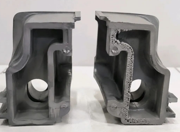
Internal voids and shrinkage cavities in thick wall plastic parts

1. Defect Characteristics

The external surface of the component may appear completely normal without visible defects. However, after cutting open the thick-wall section, irregular internal voids or cavities can be observed.

These internal voids reduce the effective load-bearing area and significantly weaken structural performance. Under mechanical stress, components may crack or fracture, while sealing parts may develop leakage problems.

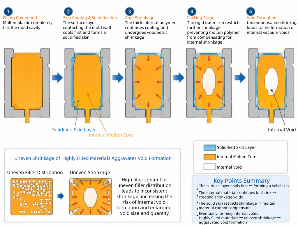
2. Formation Mechanism

After molten plastic completely fills the mold cavity, the material contacting the mold wall cools and solidifies first, creating a rigid outer shell.

The internal molten plastic continues cooling and shrinking. However, the hardened outer layer restricts further contraction.

During the packing stage, insufficient molten material is available to compensate for shrinkage, eventually forming internal vacuum voids.

For highly filled materials, uneven shrinkage between the polymer matrix and fillers can further increase the risk of void formation.

Formation mechanism of internal voids during injection molding

3. Main Causes

  • Excessive local wall thickness or sudden wall thickness transitions.
  • High material shrinkage rate.
  • Insufficient injection pressure or packing pressure.
  • Gate location too far away from thick-wall areas.
  • Poor mold venting or improper cooling channel design.

4. Improvement Solutions

① Part Design Optimization

  • Maintain uniform wall thickness throughout the component.
  • Add hollow structures, ribs, or material-reduction features in thick areas to reduce excessive material accumulation.

② Material Selection Optimization

  • Select highly filled plastics with low shrinkage and good flowability.
  • Ensure uniform filler dispersion to improve dimensional stability and reduce internal stress.

③ Injection Molding Process Optimization

  • Increase melt temperature and mold temperature to slow premature surface solidification.
  • Extend packing time and apply multi-stage packing pressure to provide continuous material compensation during cooling shrinkage.

④ Mold Design Optimization

  • Position the gate closer to thick-wall areas to shorten flow paths and reduce pressure loss.
  • Add venting channels near thick sections to improve gas removal.
  • Apply conformal cooling channels to achieve more uniform mold temperature distribution.

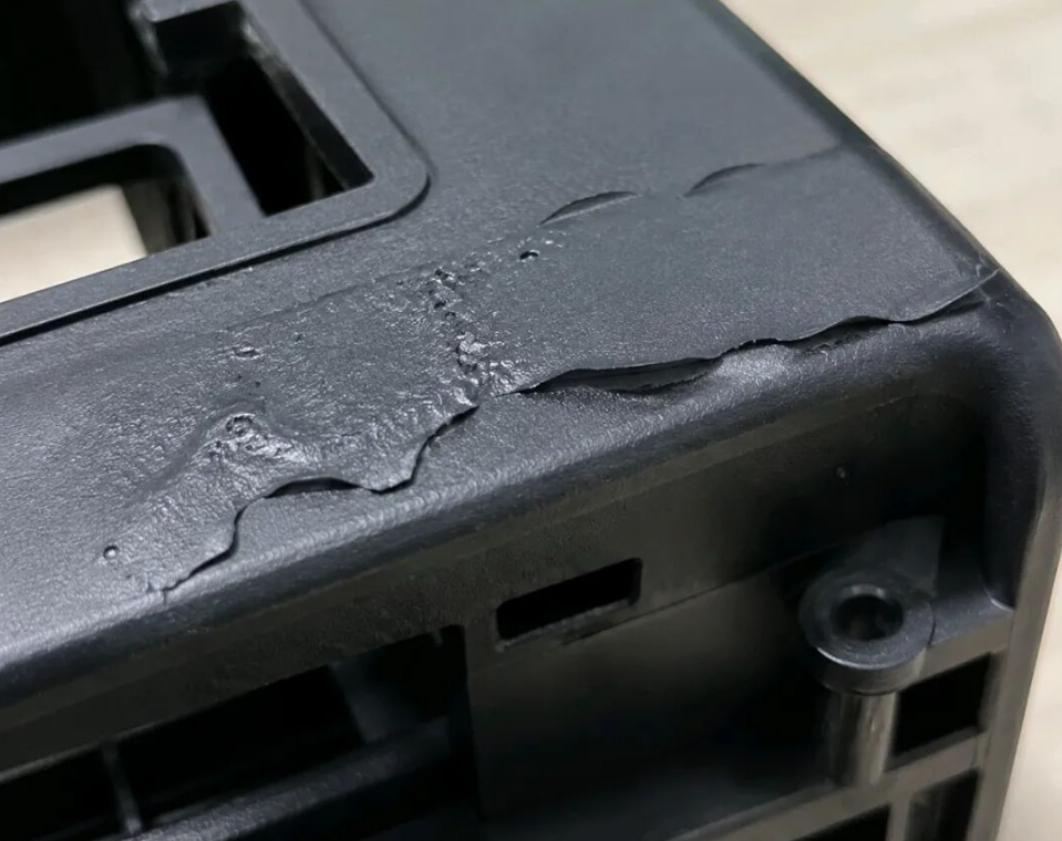
3. Delamination / Interlayer Separation: Hidden Layers That Dramatically Reduce Mechanical Strength

Delamination and interlayer separation defects in reinforced plastic parts

1. Defect Characteristics

A cross-sectional inspection reveals clear layered patterns, indicating that the material layers have failed to properly fuse together.

The layers can separate easily along the weak interface even under relatively low mechanical stress.

This defect causes a significant reduction in impact strength and flexural strength, making it one of the most severe internal defects in structural plastic components.

2. Formation Mechanism

Highly filled plastics have higher melt viscosity and poorer flowability compared with unfilled materials. During mold filling, the melt may split into multiple flow fronts.

When different melt streams with different temperatures and flow speeds meet, polymer chains may fail to properly interpenetrate and fuse together.

After cooling, a permanent separation layer is formed inside the part.

High injection speeds can generate jetting effects and unstable cavity flow, while melt backflow during filling can further intensify delamination.

3. Main Causes

  • Melt temperature and mold temperature are too low, resulting in poor material flowability.
  • Multiple gates create separated flow fronts with excessive merging angles.
  • Injection speed is too high, causing jetting defects.
  • Insufficient drying of plastic materials allows moisture to prevent proper fusion between melt layers.

4. Improvement Solutions

① Increase Temperature to Improve Flowability

  • Increase both barrel temperature and mold temperature to reduce melt viscosity and promote better fusion between flow fronts.

② Optimize Mold Runner and Gate Design

  • Reduce the number of gates where possible.
  • Minimize the angle between converging melt flows.
  • Design smooth runner transitions to prevent jetting and unstable filling behavior.

③ Adjust Injection Parameters

  • Apply multi-stage injection with controlled low-speed filling at critical areas.
  • Prevent jetting and avoid unstable melt backflow during filling.

④ Improve Material Preparation

  • Thoroughly dry raw materials before molding to remove moisture.
  • Properly extend the packing stage and use holding pressure to enhance interlayer bonding.

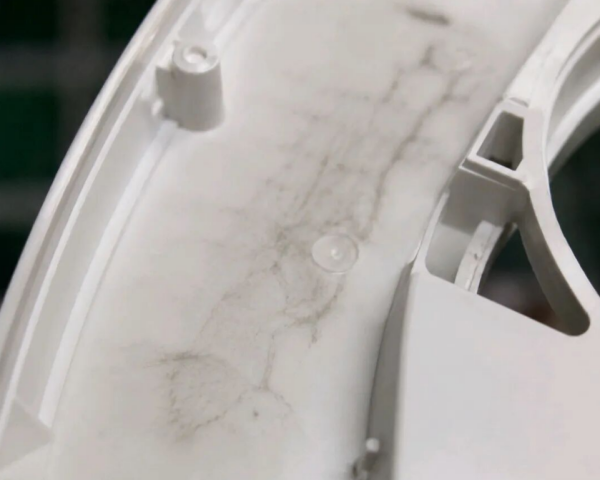
4. Cold Slugs / Internal Dark Spots: Appearance Defects Combined With Hidden Stress Concentration Areas

Cold slug and internal dark spot defects in injection molded plastic parts

1. Defect Characteristics

Dark, dull, or matte streaks and spots may appear on the surface or inside the component.

These defects are usually caused by uneven filler distribution, unstable melt flow, or insufficient fusion between different material regions.

Besides affecting appearance, these areas often have weaker bonding strength and become potential stress concentration zones, reducing the overall reliability of the component.

2. Formation Mechanism

A portion of low-temperature material accumulated in the runner system or at the front end of the barrel may enter the mold cavity together with normal molten plastic flow.

Because the cold material and hot melt have significant differences in temperature and viscosity, complete fusion cannot be achieved.

The cold slug becomes trapped inside or near the surface of the molded part, creating dark-colored spots or irregular marks.

For thick-wall components, melt flow often splits into multiple streams, increasing the possibility of cold material being trapped and forming internal defects.

3. Common Causes

  • Melt temperature or mold temperature is too low.
  • Injection speed is too slow, allowing the melt front to cool prematurely.
  • Excessive runner branching increases unnecessary melt convergence areas.
  • Poor venting causes trapped gas around cold material regions.

4. Improvement Solutions

① Increase Temperature to Reduce Thermal Differences

  • Increase barrel temperature and mold temperature to improve melting conditions and promote better fusion.

② Optimize Injection Speed

  • Increase injection speed appropriately to shorten filling time and reduce premature cooling of the melt front.

③ Improve Mold Design

  • Simplify runner systems to reduce unnecessary flow merging points.
  • Add cold slug wells to capture low-temperature material before it enters critical areas.

④ Additional Optimization

  • Improve venting at melt flow convergence areas.
  • Add appropriate flow modifiers when necessary to enhance melt compatibility and processing performance.

Conclusion: Preventing Internal Defects Requires Material, Process, and Mold Optimization

For high-filled thick-wall plastic components, internal defects are often invisible during conventional inspection but can seriously affect long-term reliability, mechanical performance, and product safety.

A successful solution requires comprehensive optimization across material selection, part design, injection molding parameters, and mold structure.

By selecting high-performance reinforced thermoplastics with controlled shrinkage, optimizing processing conditions, and improving mold design, manufacturers can significantly reduce the risks of voids, delamination, and cold slug defects.

For lightweight structural applications and metal replacement projects, controlling internal quality is essential to achieving stable performance and reliable production.

Frequently Asked Questions About High-Filled Plastic Defects

Why do glass fiber reinforced plastics develop internal voids?

Internal voids usually occur because thick sections experience uneven cooling shrinkage. When the outer surface solidifies before the core, insufficient packing compensation can create internal cavities.

Can internal defects in injection molded parts be detected visually?

No. Many internal defects such as voids and delamination are hidden beneath the surface and cannot be identified through normal appearance inspection. Advanced inspection methods such as CT scanning or section analysis are often required.

How can long fiber reinforced thermoplastics improve structural reliability?

Long fiber reinforced thermoplastics provide improved load transfer, higher impact resistance, better dimensional stability, and reduced warpage compared with conventional short fiber reinforced materials.

Need Reliable Materials for Thick-Wall Structural Components?

High-filled plastic parts require more than simply increasing filler content. Fiber length retention, filler dispersion, shrinkage control, and processing stability are critical factors for achieving reliable structural performance.

LFT-G develops long fiber reinforced thermoplastic solutions including PP-LGF, PA-LGF, PA-LCF, PPS-LGF, and other high-performance composites for automotive, industrial, appliance, and lightweight structural applications.

Explore LFT-G Materials
Untagged
Why Are Manufacturers Replacing Metal with Modified Plastics?
2026-08-07
Uncategorized

Why Are Leading Manufacturers Replacing Metal with Modified Plastics?

In 2026, the global modified plastics market is expected to exceed USD 19.476 billion, growing at an annual rate of 8.2%.

Behind this rapidly expanding market is a continuous material revolution: replacing traditional metals with advanced engineering plastics.

Key Conclusion

Whether in aerospace equipment, automotive components, or electronic products, material selection is never simply about choosing the hardest material.

The best solution depends on three key factors:

Performance requirements + Application conditions + Overall cost efficiency

1. Metal vs. Engineering Plastics: The Natural Toughness of Metals

Three Major Limitations of Traditional Metal Parts

Limitation Specific Performance Cost Impact
Heavy Weight Density is 3–5 times higher than engineering plastics Higher transportation and assembly costs
Difficult Processing Requires cutting, stamping, welding and other processes Higher machining and labor costs
Corrosion Risk Requires coating and anti-rust treatment Additional maintenance costs

Why Ordinary Plastics Cannot Replace Metals

  • Temperature resistance: deformation and performance loss may occur under long-term heat exposure.
  • Low-temperature performance: brittleness and cracking may occur under cold impact conditions.
  • Strength and rigidity: insufficient mechanical performance for structural applications.
  • Dimensional stability: thermal expansion affects precision applications.

2. Three Core Application Scenarios of Modified Plastics

Scenario 1: Household Appliances — PA and PET Reinforced Materials

Household appliances require excellent rigidity, impact resistance, dimensional stability and electrical safety performance.

Performance Standard PA/PET Glass Fiber Reinforced PA/PET Improvement
Tensile Strength 30–40 MPa 80–140 MPa 2–4 times higher
Heat Distortion Temperature 60–80°C 120–160°C +40–70°C
Impact Resistance Average Excellent Multiple improvement
Key Insight:
When glass fiber content reaches 20–30%, the material achieves excellent rigidity and heat resistance. However, excessive fiber content may increase brittleness and reduce toughness.

Scenario 2: Electronic Connectors — PBT Materials as Industry Solutions

Safety Requirement Requirement Modified PBT/PA Performance
UL94 Flame Rating V-0 level Can achieve V-0 flame retardancy
CTI Value ≥600V for high voltage applications Special formulations can reach 600V+
Temperature Range -40°C to 200°C Covered by modified materials
Electrical Stability Long-term insulation Stable electrical performance

Scenario 3: Automotive Engine Components — PPS and High Performance PA

Comparison Aluminum Alloy Modified Plastics (PPS/PA) Advantage
Weight 100% ≈60% Up to 40% weight reduction
Cost 100% ≈50% Lower overall cost
Processing Multiple processes Injection molding Higher efficiency
Durability Requires protection Corrosion resistant Reduced maintenance
Modified PPS and PA materials can combine multiple functions into one injection-molded component, reducing secondary machining, drilling and finishing processes.

3. Industry Insights

There Is No Perfect Material — Only the Best Material for Each Application

Modified plastics are not simply replacing metals everywhere. Instead, engineers select the most suitable material based on different working conditions.

  • Home Appliances: insulation, appearance and durability
  • Electronic Connectors: electrical safety and dimensional stability
  • Automotive Components: lightweight design, heat resistance and reliability
Every material selection decision is a balance between:

Performance and Cost.

Conclusion

With industries continuously pursuing lightweight design, higher efficiency and cost optimization, modified engineering plastics are becoming an increasingly important alternative to traditional metals.

The future of material selection is not about whether plastics can completely replace metals, but about finding the most suitable material solution for every application.

Customer Project LFT Solution for Car Fan shrouds
2026-07-29
Uncategorized
PA6-LGF30 Automotive Fan Shrouds | Long Glass Fiber Reinforced PA6 for Engine Cooling Systems

PA6-LGF30 Automotive Fan Shrouds for Lightweight & High-Performance Cooling Systems

Long glass fiber reinforced PA6 engineered for strength, durability, and efficient automotive cooling applications.

1. Why Automotive Fan Shrouds Matter

The fan shroud is an essential component of an automotive engine cooling system. It directs airflow through the radiator, improving cooling efficiency while protecting the cooling fan from external damage.

As modern vehicles become lighter and more energy-efficient, manufacturers are replacing traditional materials with high-performance engineering plastics capable of delivering superior mechanical performance without increasing weight.

2. Why Choose PA6-LGF30?

2.1 Long Glass Fiber Reinforcement

PA6-LGF30 combines Polyamide 6 with 30% long glass fibers, creating a reinforced internal structure that provides significantly higher stiffness and impact resistance compared with conventional short glass fiber reinforced materials.

2.2 Performance Advantages

  • Excellent stiffness and structural strength
  • Outstanding impact resistance
  • High heat resistance for engine compartment environments
  • Superior dimensional stability
  • Reduced vibration and noise
  • Excellent fatigue resistance during long-term service
  • Supports automotive lightweighting initiatives

3. Engineering Challenges of Fan Shrouds

3.1 High Temperature Environment

Fan shrouds are continuously exposed to elevated temperatures generated by the engine and radiator. Materials must maintain stiffness and dimensional accuracy even after long-term thermal exposure.

3.2 Dynamic Mechanical Loads

Vehicle vibration, road impact, and continuous airflow generate repeated mechanical loading. PA6-LGF30 provides excellent fatigue performance, ensuring reliable long-term operation.

3.3 Dimensional Precision

Maintaining the correct clearance between the fan blades and shroud is critical for cooling efficiency and noise reduction. Long glass fiber reinforcement minimizes warpage and improves dimensional stability.

4. Why Long Glass Fiber Performs Better

Unlike conventional short glass fiber reinforced plastics, long glass fibers form a continuous reinforcing network inside the polymer matrix. This allows stress to be distributed more evenly throughout the component, improving impact strength, fatigue life, and overall structural integrity.

Compared with Short Glass Fiber Materials:
  • Higher impact strength
  • Improved creep resistance
  • Better fatigue durability
  • Lower warpage
  • Greater design freedom for complex injection molded parts

5. Typical Applications

  • Automotive radiator fan shrouds
  • Electric cooling fan housings
  • HVAC air guide components
  • Engine compartment structural parts
  • Electric vehicle cooling system components

6. About Xiamen LFT Composite Plastics

6.1 Long Fiber Composite Material Manufacturer

Xiamen LFT Composite Plastics Co., Ltd. specializes in manufacturing long glass fiber reinforced thermoplastic materials, including PP, PA6, PA66, TPU, PPS, PPA, and long carbon fiber reinforced composite materials for demanding engineering applications.

6.2 Industries We Serve

Our materials are widely used in automotive, new energy vehicles, power tools, industrial equipment, consumer electronics, and structural engineering applications requiring lightweight design and exceptional mechanical performance.

7. Why Choose Our PA6-LGF30?

  • Over 20 years of long fiber composite manufacturing experience
  • Consistent fiber length for superior mechanical performance
  • Customized formulations available
  • Global technical support
  • Ideal for automotive lightweight solutions

8. Contact Us

Looking for high-performance PA6-LGF30 materials for automotive applications?

Contact us for technical datasheets, material recommendations, sample evaluation, and engineering support.

Contact Us
Untagged